Now comes the difficult part.
Since gears in the movement assembly are the most important part, it needed to be precise. I could just go away with the rough 'looking right ' gear profile and dimensions but for the future, I went out searching for information on how gear profiles are calculated. And for the spoiler, its wasn't easy, at least the way I took.
So to understand how the gears are related to each other, another assembly was built.

First thought, it was rather simple than what I anticipated, but I can take this as good sign because less complexity means less work I need to do. Yay I guess?
Though, a few interesting relations are implemented here.
These two gears are only semi-connected with friction. Reason being in order to manually adjust time, minute and hour hands need to be separated from the movement. But also in order for hands to properly display time, they need to be connected to the movement. So the way to go is to friction fit them. Not so bad idea, but with one assumtion - no excessive manual time adjustment is expected.
Another interesing thing happens with the ratchet wheels, or power reserve winding system. In this case, there is some sort of one-way clutch that physically isolates ratchet wheels and movement. This difference to that of motion works above is probably due to frequency of use. The power reserve of this watch lasts about a day and rubbing of surfaces everyday won't last long even for metal.
Went off track for a bit but back to the gear calculation.
With a bit of research, I was able to find a website with detailed equations. Link - A big thanks to the authors of the website. Give a visit if you want to know how to calculate involute gear profile.
Overall, it wasn't easy, but finally got to the point where I have the first calculation of a pair.
Though number seems quite differnet form the original, if this brings copyright issue, contact me and I will sort that out.
Twelve points along the profile should be sufficient for my case. I will be able to produce curvature with these numbers in the future if needed. But now... here comes the manual work. Applying those numbers to the sketch and it was... ya it took long. Twelve dimensions times three to properly fix all the point in the sketch.
So, I decided to try a new method to hpefully make things easy. There is a feature called 'Equation' in Solidworks where external numbers can be imported to define dimensions in sketches. This should make things easier a bit if can't automate all. And in the future if I need to change those numbers, then it would be just copy/paste and update.
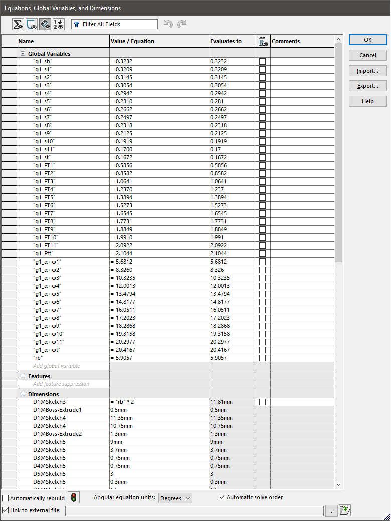
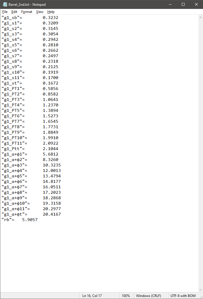
It simply created a text file with variable names. But there is one thing to watch out for - the format matters in this file where “” is different from "". Ya. Now that I have the first pair done, it was just simple copy and paste with proper dimensions for other pairs.
Whoa this took long...
Later I figured that there is a add-on in Autodesk Fusion 360 that does the calculation for me. With just a few numbers, it will calculate profile and build the appropriate gear for me! Only if I new it sooner... And looks like Solidworks has library of standard gears but this is a special case I assume.
Escapement assembly will be done in the future as it requires different approach.
The next step is to validate whether the movement works properly or not.